Home Lab
published: 12th of February 2024
Intro
Greeting fellow nerds! In this the 2024th year of our lord, Kermit J Frog. I am commited to upskilling on Observability and Kubernetes. To achieve this, I am building out my home lab and using the ways of DevOps.
Technologies
Before I can start building a Kubernetes cluster, I need to build out all the supporting services. The following table lists the hardware and software technology I am using in my lab.
| Component | Technology |
|---|---|
| Routing | VyOS |
| Firewall | VyOS |
| Wireless | Ubiquiti |
| Switching | Mikrotik |
| Remote Access | ZeroTier |
| DNS | PiHole |
| DHCP | Kea |
| NTP | VyOS |
| PKI | VyOS |
| Virtualization | Proxmox |
| Storage | TrueNas Scale |
| Operating System | Ubutuntu |
| Containerization | Docker |
| Config Management | SaltStack |
| Intrastructure as Code | Terraform |
| Logging/Monitoring | OpenSearch |
| App Service | Kubernetes |
Architecture
I created a few diagrams to help visualize the network.
Physical Network
The physical network is a simple setup with three compute nodes, and a single switch. The following diagram shows the physical network layout.
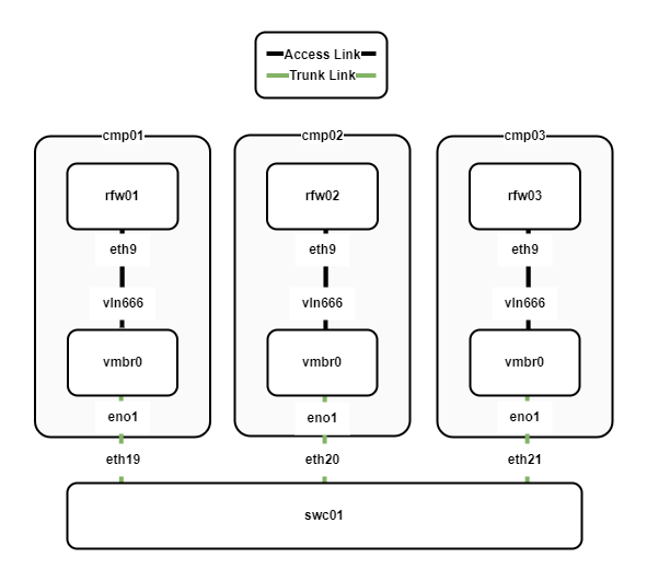
The following points describe the physical network layout:
- Three compute nodes cmp01-03 are running the Proxmox hypervisor and utilise Open vSwitch as the virtual switch.
- The compute nodes connect to swc01 via a trunk link which allows multiple VLANs to be shared between the compute nodes.
- Each compute node has a VyOS virtual router/firewall. The VyOS VMs are configured as the default gateway for all the internal networks.
VLANs
Functions are logically seperated into VLANs. The following diagram shows the VLAN assignment between the VyOS routers and the hypervisor switch.
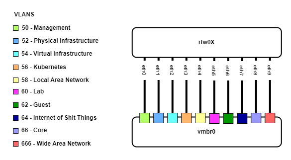
The following points describe the VLAN assignments:
- Three VyOS VMs (rfw01-03) have 10 interfaces, one for each VLAN.
- Each interface connects to the Open vSwitch bridge and is assigned to a VLAN.
Virtual Router Redundancy Protocol (VRRP)
VRRP is used as the first-hop redundancy protocol. The following diagram shows the VRRP configuration between the VyOS routers.
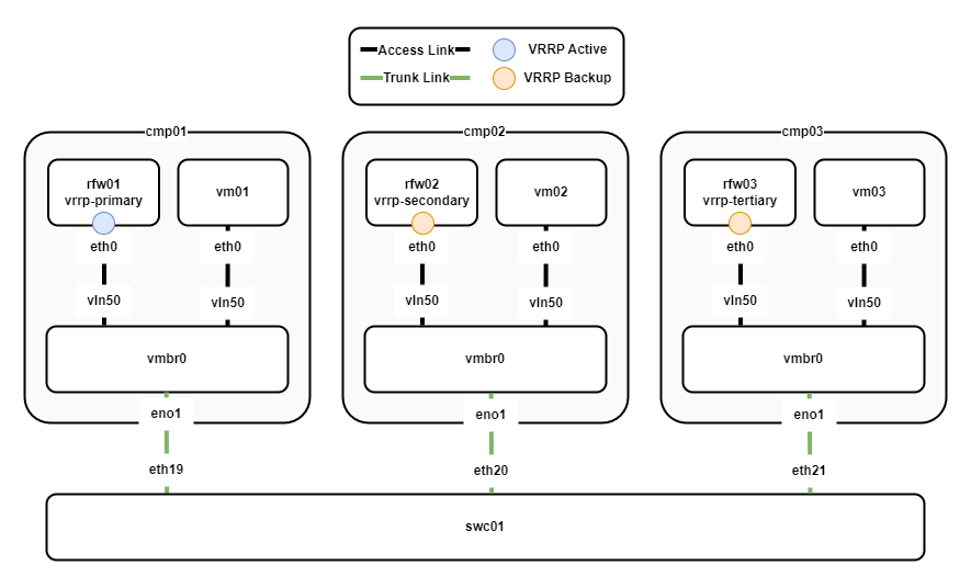
The following points describe the VRRP configuration:
- rfw01 is the active router and rfw02/03 backup routers.
- The VRRP priority of the routers is set so that rfw01 has the highest priority, rfw02 the second highest, and rfw03 the lowest.
- Preempt is enabled, so if rfw01 fails, rfw02 will take over as the active router. When rfw01 comes back online, it will again become the active router.
- Virtual machines vm01-3 use the VRRP virtual IP of the active router as their default gateway.
Routing
The IS-IS routing protocol is used to share routing information between the VyOS routers. The following diagram outlines the routing configuration for both the LAN and WAN.
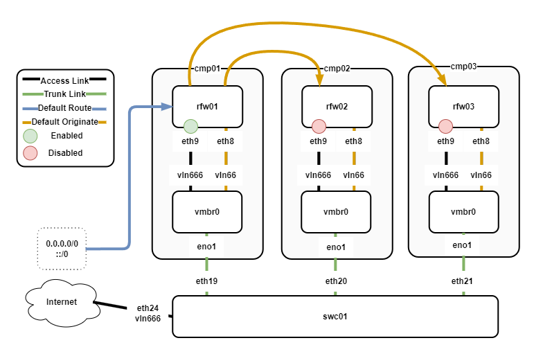
The following points describe the routing configuration:
- rfw01/02/03 have an IS-IS neighbourship over eth8.
- All VyOS routers have eth9 configured to connect WAN, however, only rfw01 has eth9 enabled.
- rfw01 receives the default route from the ISP.
- rfw01 originates the default route for IPv4/6 via IS-IS.
- rfw02/03 receive the default routes from rfw01 via IS-IS.
IPAM
I am running a dual-stack network with IPv4 and IPv6. Each VLAN has a /23 IPv4 CIDR and a /64 IPv6 CIDR. The following table outlines the IPAM for the network.
| Description | ID | IPv4 CIDR | IPv6 CIDR |
|---|---|---|---|
| MGMT | 50 | 10.100.50.0/23 | fd00:10:100:50::/64 |
| Physical Infra | 52 | 10.100.52.0/23 | fd00:10:100:52::/64 |
| Virtual Infra | 54 | 10.100.54.0/23 | fd00:10:100:54::/64 |
| Kubernets | 56 | 10.100.56.0/23 | fd00:10:100:56::/64 |
| LAN | 58 | 10.100.58.0/23 | fd00:10:100:58::/64 |
| LAB | 60 | 10.100.60.0/23 | fd00:10:100:60::/64 |
| Guest | 62 | 10.100.62.0/23 | fd00:10:100:62::/64 |
| IOT | 64 | 10.100.64.0/23 | fd00:10:100:64::/64 |
| CORE | 66 | 10.100.66.0/23 | fd00:10:100:66::/64 |
| LOOPBACKS | 68 | 10.100.68.0/23 | fd00:10:100:68::/64 |
Physical Infrastructure
The following table lists the addresses for the physical infrastructure.
| Device | Description | IPv4 | IPv6 |
|---|---|---|---|
| vrrp | gateway | 10.100.52.1/23 | fd00:10:100:52::1/64 |
| rfw01 | core router/firewall | 10.100.52.2/23 | fd00:10:100:52::2/64 |
| rfw02 | core router/firewall | 10.100.52.3/23 | fd00:10:100:52::3/64 |
| rfw03 | core router/firewall | 10.100.52.4/23 | fd00:10:100:52::4/64 |
| swc01 | switch | 10.100.52.5/23 | fd00:10:100:52::5/64 |
| swc02 | switch (future) | 10.100.52.6/23 | fd00:10:100:52::6/64 |
| pmx01 | compute | 10.100.52.10/23 | fd00:10:100:52::10/64 |
| pmx02 | compute | 10.100.52.11/23 | fd00:10:100:52::11/64 |
| pmx03 | compute | 10.100.52.12/23 | fd00:10:100:52::12/64 |
| nas01 | storage | 10.100.52.13/23 | fd00:10:100:52::13/64 |
| nas02 | storage (future) | 10.100.52.14/23 | fd00:10:100:52::14/64 |
Virtual Infrastructure
The following table lists the IP addresses for the virtual infrastructure.
| Device | Description | IPv4 | IPv6 |
|---|---|---|---|
| vrrp | gateway | 10.100.54.1/23 | fd00:10:100:54::1/64 |
| rfw01 | core router/firewall | 10.100.54.2/23 | fd00:10:100:54::2/64 |
| rfw02 | core router/firewall | 10.100.54.3/23 | fd00:10:100:54::3/64 |
| rfw03 | core router/firewall | 10.100.54.4/23 | fd00:10:100:54::4/64 |
| dns01 | dns server | 10.100.54.11/23 | fd00:10:100:54::11/64 |
| dns02 | dns server | 10.100.54.12/23 | fd00:10:100:54::12/64 |
| dcp01 | dhcp server | 10.100.54.13/23 | fd00:10:100:54::11/64 |
| dcp02 | dhcp server | 10.100.54.14/23 | fd00:10:100:54::12/64 |
| wlc01 | wireless controller | 10.100.54.15/23 | fd00:10:100:54::15/64 |
| slt01 | salt master | 10.100.54.16/23 | fd00:10:100:54::16/64 |
| slt02 | salt proxy | 10.100.54.17/23 | fd00:10:100:54::17/64 |
Core
The following table lists the IP addresses for the core network.
| Device | Description | IPv4 | IPv6 |
|---|---|---|---|
| rfw01 | core router/firewall | 10.100.66.1/32 | fd00:10:100:66::1/128 |
| rfw02 | core router/firewall | 10.100.66.2/32 | fd00:10:100:66::2/128 |
| rfw03 | core router/firewall | 10.100.66.3/32 | fd00:10:100:66::3/128 |
Loopbacks
The following table lists the loopback IP addresses.
| Device | Description | IPv4 | IPv6 |
|---|---|---|---|
| rfw01 | core router/firewall | 10.100.68.1/32 | fd00:10:100:68::1/128 |
| rfw02 | core router/firewall | 10.100.68.2/32 | fd00:10:100:68::2/128 |
| rfw03 | core router/firewall | 10.100.68.3/32 | fd00:10:100:68::3/128 |
Outro
That's all for now. I will keep updating this post as I progress through the build.
✌️ Peace out nerds. Stay weird! ✌️