Cloud Notes: AWS VPC
updated: 7th of January 2024
published: 2nd of February 2023
Intro
AWS Virtual Private Clouds (VPCs) are a regional service that provide isolated networking for cloud infrastructure.
VPCs are secure by default. Traffic inbound and outbound of a VPC is blocked unless it is explicitly allowed.
There are 2 types of Tenancy's for a VPC.
| Tenancy Type | Description | Extra Cost |
|---|---|---|
| Default | VPC resources are provisioned across shared infrastructure | False |
| Dedicated | VPC resources are provisioned on dedicated infrastructure | True |
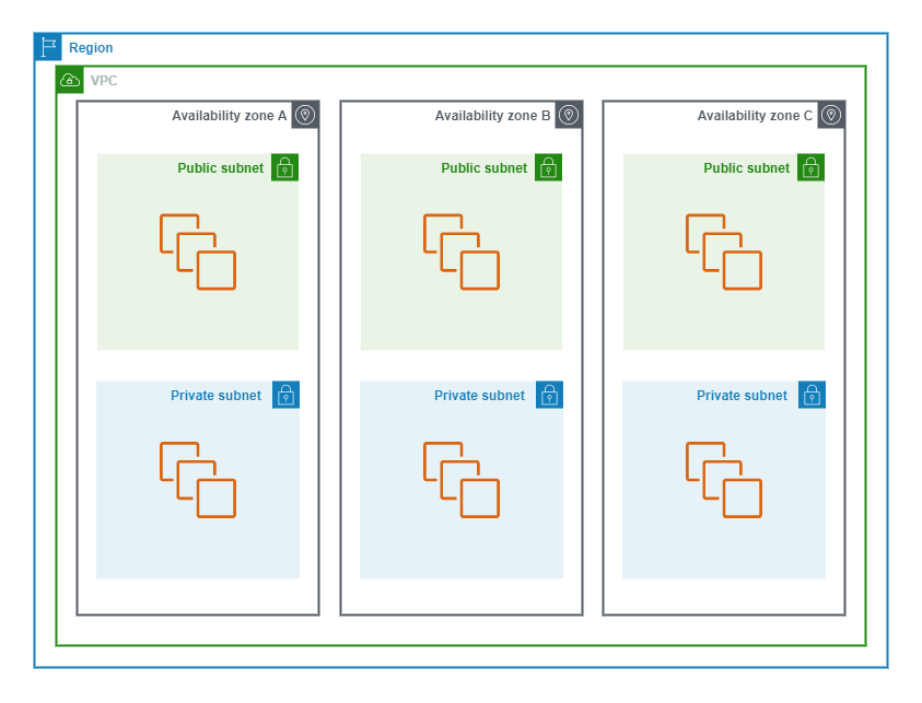
The following diagram shows the conceptual layout of a VPC in AWS.
Default VPC
Each Region has a pre-configured VPC with a Public Subnet in Each Availability Zone, an Internet Gateway, and DNS resolution enabled. This allows customers to quickly spin up EC2 instances that have access to the Public Internet.
Custom VPC
A Custom VPC is just a VPC that you configure yourself seperately to the Default VPC.
Availability Zone
Each Region has multiple Availability Zones and a VPC Spans all Availability Zones in a Region.
CIDR Block
VPCs are assigned IP address CIDR blocks. Hosts deployed in the VPC are assigned addresses from within the CIDR range.
IPv4 CIDR
- IPv4 CIDR blocks must be assigned from the RFC 1918 private address range.
- The maximum size is a /16
- The minimum size is a /28
- A VPC can have 1x Primary IPv4 CIDR block with optional secondary CIDR block(s)
IPv6 CIDR
A VPC can optionally assign a single IPv6 CIDR block. IPv6 CIDR block can either be assigned from a BYO IPv6 pool or assigned by AWS. If using AWS assigned IPv6 CIDR blocks you have no choice in which block is assigned.
- Must be /56 in size.
- All IPv6 addresses are publicly routable by default, but explicit configuration is still required to enable access to/from them to the internet.
Subnets
VPC Subnets have the following Characteristics.
- Are constrained to a single Availbility Zone and are AZ resilient.
- Must be a subset of the VPC CIDR.
- Cannot overlap other subnets and must be unique within a VPC.
- Subnets have IP reachability to other subnets within a VPC.
- Subnets are private by default and require explicit configuration to make them public.
Reserved IPs
AWS reserves 5 IP addresses in each subnet.
- Network/First Address
- Network Address +1 - VPC Router
- Network Address +2 - VPC DNS Resolver
- Network Address +3 - Reserved for future use
- Broadcast/Last Address
Auto Address Assignment Options
Public IP addresses can be automatically assigned to instances when they are created. The following options must be enabled for IPv4 and IPv6 subnets for this to happen.
- Auto Assign Public IPv4 address - Assigns an IPv4 Elastic IP address.
- Auto Assign IPv6 address - This must be enabled for instances to get an IPv6 address. (All IPv6 Addresses are Public)
Subnet Designation
How routing is configured for a subnet determines it's designation.
| Designation | Characteristics |
|---|---|
| Public Subnet | Has a direct route to an Internet Gateway and can access the Public Internet. |
| Private Subnet | Does not have a direct route to an Internet Gateway and requires a NAT device to access the Public Internet |
| VPN-Only Subnet | Has a route to a Site-to-Site VPN connection and does not have a route to an Internet Gateway. |
There are 3 types of IP Addressing for hosts in a subnet.
- IPv4 Only
- IPv6 Only
- Dual Stack (IPv4 + IPv6)
IPv4 Subnet
- IPv4 addresses can only be assigned from the RFC 1918 address blocks.
- An IPv4 subnets size can range from a /28 up to a /16 which is the same size as a VPC. The subnet must also be from the same CIDR range as the VPC.
- Publicly routable IPv4 addresses are assigned to Elastic IP's but they are NOT configured directly on an EC2 instance. They are used during NAT outbound to the internet.
The following table lists the RFC 1918 address blocks.
| Address Class | Prefix |
|---|---|
| A | 10.0.0.0/8 |
| B | 172.16.0.0/12 |
| C | 192.168.0.0/16 |
IPv6 Subnets
- An IPv6 subnet must be a /64 in size and be from the same CIDR range as the VPC.
- There are 256 available /64 subnets for use in a /56 VPC CIDR.
- All IPv6 addresses are publicly routable and NAT is not required to access the internet.
IPv4 vs IPv6 Services
Not all AWS services have feature parity for IPv6 as with IPv4.
VPC DNS
DNS services can be provided within a VPC. The DNS service has the following characteristics.
- DNS within a VPC is provided by the Route53 service.
- The DNS resolver IP address is the Subnet IP +2.
- The enableDnsHostnnames setting must be enabled allow VPC instances to have public hostnames. This setting is Disabled by default.
- The enableDnsSupport setting allows instances to use the DNS resolver for name resolution. This setting is Enabled by default.
BYO CIDRs
You can bring you own IPv4 and IPv6 CIDRs for use in AWS with the following considerations.
- Imported prefixes are advertised by BGP from the AWS with the ASNs 16509 or 14618.
- Imported prefixes MUST be Resource Public Key Infrastructure (RPKI) validated and, have a Route Origin Authorisation (ROA) with the issuing Regional Internet Registry (RIR) permitting AWS to advertise the prefixes from their ASN's.
- A /24 is the smallest IPv4 prefix you can bring.
- A /48 for publicly advertised and a /56 for non-publicly advertised IPv6 prefixes are the smallest you can bring.
- CIDRs are imported Per-Region so A CIDR is only available in the Region it is imported into.
- There is a 5 IPv4 and IPv6 CIDR limit Per-Region Per-Account.
- It is NOT possible to share IPv4 or IPv6 CIDRs with other accounts using AWS Resource Access Manager (RAM).
VPC DHCP
DHCP in a VPC is used to provide the IP, subnet mask and gateway addressing.
DHCP Option Set
Within a VPC you can customise the DHCP settings via a DHCP Option Set. The following options are configurable.
- Domain Name
- DNS Servers
- NTP Servers
- NetBIOS Name Servers
- NetBIOS Node Type
DHCP Option Sets have the following characteristics.
- Each subnet is assigned a DHCP option set.
- DHCP Option sets are immutable and cannot be changed once created. To edit them you must create a new option set and delete the old one.
- You can create multiple option sets. However, only a single option set can be assigned to a VPC at a time.
VPC Router
The VPC router is a virtual router within a VPC which is fully managed by AWS. The VPC Router has the following characteristics.
- Highly available across all AZs within a region.
- Routes traffic between subnets in a VPC as well as to/from a VPC.
- The VPC router uses the subnet +1 address for each subnet in a VPC as the default gateway.
- The Routing behavour of the VPC router can be modified using Route Tables.
Route Table
Route Tables are used to define routing behavour for a VPC. A Route Table has the following characteristics.
- Route Tables are associated with subnets. There are 2 types of route tables. The default Main table and Custom tables.
- Subnets can only be associated with 1 Route Table. Changing a subnet to use a Custom Table removes the association of the Main Table.
- A subnet must have a route table, so if you dissacociate a Custom Table, the Main Table will be automatically re-associated.
- Routes are select based on the longest match prefix length. More specific routes are preferred over less specific routes. IE: a /32 is preferred over a /16.
- By default, the main route table has a route for the VPC CIDR for both IPv4 and IPV6 if it is enabled. This allows traffic to route between all subnets in a VPC.
- The target for these routes are local which means, sourced from the VPC.
- Route Tables can be associated with different types of Gateways.
The following table shows an example Route Table.
| Destination | Target |
|---|---|
| 10.18.192.0/18 | local |
| 2600:1f16:190:6a00::/56 | local |
Gateway Route Table
When associating a route table with a VGW or IGW, the RT is known as a Gateway Route Table.
Subnet route tables allow you to control VPC routing behavour on the Egress direction. Gateway route tables allow you to control the routing behavour on the Ingress direction to a VPC.
A common use for a Gateway Route Table is to route traffic from from an IGW to a security appliance for inspection.
Route Selection
Route selection is AWS is pretty straight forward. There are some different considerations depending on the services that are in use. The goal is to find a single best route to a destination.
VPC Route Table
Route priority in a VPC is determined as in the following order (from highest to lowest priority).
- Longest prefix (most specific) match.
-
When multiple equal length prefix matches exist,
routes are prefered based on the route type:
- Static routes.
- Prefix list routes.
- VGW Propagated routes.
VGW Propagated Routes
When a VGW is attached to a VPC, the following route selection rules apply for propagated routes (from highest to lowest priority).
- BGP propagated routes from a Direct Connect (DX).
- Static routes to a Site-to-Site VPN connection.
- BGP propagated routes from a Site-to-Site VPN connection.
-
When multiple equal length BGP learned prefix matches exist,
routes are prefered based on a BGP attribute:
- Shortest AS_PATH.
- Lowest MED.
Network ACL
Network ACLs (NACLs) logically sit around a Subnet filtering Inbound and Outboud of the Subnet boundary.
The following diagram is a visual representation of a NACL.
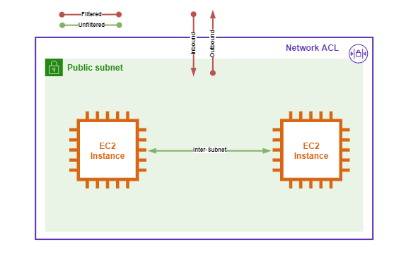
Network ACLs have the following characteristics.
- Network ACLs are Stateless.
- Network ACLs match traffic based on a 5-tuple match criteria: Source + Destination IP, Source + Destination Port, Protocl.
- NACLs are configured in 2 directions: Inbound and Outbound.
- The direction of traffic (Inbound or Outbound) is determined by which host is the source of the traffic.
- A subnet can only be associated with a single NACL.
- By default, all traffic is Allowed Inboud and Outbound through the Default NACL.
- Rules are processed in order from the Lowest to the Highest rule number.
- Rule processing is stopped when a rule is matched.
- Implicit rules are denoted with a *
- There are 2 actions that can be performed on matched traffic: Allow or Deny.
The following table shows and example Inbound Network ACL.
| Rule Number | Type | Protocol | Port Range | Source | Allow/Deny |
|---|---|---|---|---|---|
| 100 | All traffic | All | All | 0.0.0.0/0 | Allow |
| 101 | All traffic | All | All | ::/0 | Allow |
The following table shows and example Outbound Network ACL.
| Rule Number | Type | Protocol | Port Range | Destination | Allow/Deny |
|---|---|---|---|---|---|
| 100 | All traffic | All | All | 0.0.0.0/0 | Allow |
| 101 | All traffic | All | All | ::/0 | Allow |
Custom NACLs
When creating a custom NACL the following criteria applies.
- By default, all traffic is Denied in/out through a Custom Network ACL.
- Custom NACLs are not associated with any subnets when initially created.
Security Group
Security Groups logically sit around an Elastic Network Interface (ENI) filtering Inbound and Outboud of the ENI boundary.
The following diagram is a visual representation of a Security Group.
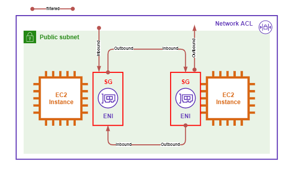
Security Groups have the following characteristics.
- Security Groups have an Implicit Deny that block all traffic that is not Explicitly allowed.
- Security Groups are Statefull and return traffic is implicitly allowed.
- Security Groups are configured in 2 directions: Inbound and Outbound.
- Security Groups can match traffic based on a 5-Tuple match. They can also match Application Layer protocols and other logical AWS resources (including themself).
- Default Security Groups have an implicit Allow rule that permits all traffic from anything in the Security Group.
- Security Groups are attached to Elastic Network Interfaces (ENIs) NOT to EC2 Instances.
The following table shows and example Inbound Security Group.
| Name | Security group rule ID | IP version | Type | Protocol | Port range | Source | Description |
|---|---|---|---|---|---|---|---|
| - | sgr-0aec7b2c7b9f8d6eb | - | All traffic | All | All | sg-0fba9702a97ac5405 / default | - |
The following table shows and example Outbound Security Group.
| Name | Security group rule ID | IP version | Type | Protocol | Port range | Destination | Description |
|---|---|---|---|---|---|---|---|
| - | sgr-034c70fb26e78345b | Ipv4 | All traffic | All | All | 0.0.0.0/0 | - |
| - | sgr-02bde64e798ce5123 | Ipv6 | All traffic | All | All | ::/0 | - |
NAT Gateway
NAT Gateways are used to provide EC2 instances in Private Subnet access to AWS Public Services and the internet.
The following points list the characteristics of a NAT Gateway.
- NAT Gateways are AZ Resilient. To achieve NAT Gateway resilience, a NAT Gateway is required in each Availability Zone in a Region. Private Subnets must have their Route Table point to the NAT Gateway within the same AZ.
- NAT Gateways are deployed in Public Subnets.
- Nat Gateways allow outbound and return traffic from Private Subnets. Unsolicited inbound traffic is not allowed.
- NAT Gateways can Scale from 5 up-to 45 Gbps of throughput.
- NAT Gateways support up-to 55k simultanious connections to each destination. If this is exceeded, the ErrorPortAllocation metric is triggered CloudWatch.
- Mulitple NAT Gateways can be deployed within an AZ to aid in scalling.
- NAT Gateways use static Elastic IPs that CANNOT be changed. To use a different Elastic IP a New NAT Gateway must be deployed.
- NAT Gateways are billed Per-Instance, Per-Second. And also, Per-Gbps processed.
- NAT Gateways CANNOT be used across VPC Peers, Site-to-Site VPNs, or AWS Direct Connects.
- NACL are used to secure NAT Gateways at the Subnet Level. Security Groups are NOT supported on NAT Gateways.
The following diagram shows a typical NAT Gateway deployment.
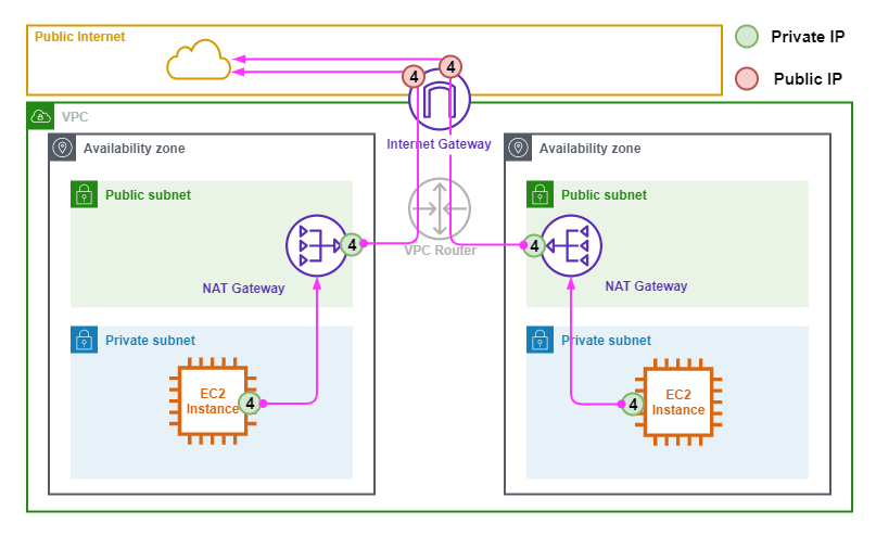
The following points describe the above diagram.
- NAT Gateways need a Public Elastic IP adress so are deployed in a Public Subnet.
- NAT Gateways do NOT have any directly assigned Public IPv4 Addresses.
- An Elastic IP is translated for the NAT Gateways Outside interface to and from the internet.
- The EC2 Instances in the Private Subnets use the NAT Gateway in the Public Subnet as their Default Route to access the Internet.
Internet Gateway
Internet gateways sit at the edge of a VPC and the AWS Public Zone allowing access to the Public Internet and to AWS Public Services.
Internet Gateways are Highly Available and Scalable across all Availability Zones in a Region. They are also fully managed by AWS.
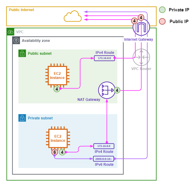
The following points describe the above image.
- The Internet Gateway permits IPv4 and IPv6 for both the inbound and outbound directions.
- The EC2 Instance in the Public Subnet has an RFC1918 private address that has a 1:1 Static NAT to a Public Elastic IP on the Internet Gateway.
- The NAT gateway sits in the Public Subnet and has a Private IPv4 address on it's Outside Interface. The Private address is translated to a Public Elastic IP address at the Internet Gateway.
- The EC2 Instance in the Private Subnet has Dual-Stack IPv4 and IPv6 addresses.
- The EC2 Instance in the Private Subnet uses the NAT Gateway as it's default route for IPv4 routes.
- The EC2 Instance in the Private Subnet uses the Internet Gateway as it's default route for IPv6 routes.
Egress-Only Internet Gateway
There can only be a single Internet Gateway Per-VPC. However, a VPC can also have a single Egress-Only Internet Gateway which is used to restrict IPv6 Subnets to Outbound initiated traffic flows.
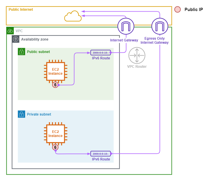
The following points describe the above image.
- The Public and Private Subnets are IPv6-Only Subnets.
- The EC2 Instance in the Public Subnet uses the Internet Gateway as it's default route for IPv6 traffic.
- Both Outbound and Inbound initiated traffic flows are permitted through the Internet Gateway.
- The EC2 Instance in the Private Subnet uses the Egress-Only Internet Gateway as it's default route.
- The EC2 Instance in the Private Subnet is restricted to Outbound initiated traffic flows.
PrivateLink
AWS PrivateLink allows you to connect to 3rd Party Provider Services, supported AWS services, and your on-premises network without traversing the public internet.
The following considerations are relevant to PrivateLink.
- PrivateLink powers both Gateway and Interface Endpoints.
- Only IPv4 and TCP protocols are supported.
- Private DNS can be used to override Public DNS records for PrivateLink services.
Gateway Endpoint
Gateway Endpoints allow instances in Private subnets to access supported Public Services without traversing the internet. The current supported services are S3 and DynamoDB.
The following points list the characteristics of Gateway Endpoints.
- Allow Private Access to Public Services.
- Gatway Endpoints are a Regional Service and provide access to supported services within the Region they are deployed.
- Gateway Endpoints are Higly-Available across all Availability Zones within a Region.
- Gateway Endpoints are deployed at the VPC level and Subnets are Assigned to a Gateway Endpoint.
- Assigned Subnets have an AWS managed Prefix List added to their Route Table that points the the Gateway Endpoint.
- Endpoint Policies are used to control what resources the Gateway Endpoint can access.
- Gateway Endpoints are non-transitive and can only be used by resources within the VPC they are deployed.
- Gateway Endpoints have no associated cost.
The following diagrams shows a typical Gateway Endpoint deployment.
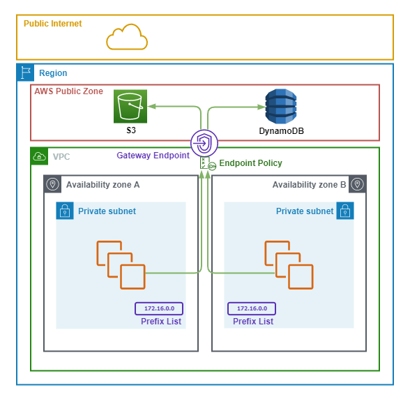
The following points summarize the above diagram.
- A Gateway Endpoint is deployed in the VPC which is available across all Availability Zones.
- Both Private Subnets are associated with the Gateway Endpoint and have an AWS managed Prefix List added to their Route Tables. The Prefix List points routes for S3 and DynamoDB toward the Gateway Endpoint.
- There is an Endpoint Policy applied to the Gateway Endpoint which restricts access to specific resources.
- EC2 instances use the Gateway Endpoint to access S3 and DynamoDB without traversing the public internet.
Interface Endpoint
Interface Endpoints provide private access to services that integrate with PrivateLink except DynamoDB. The list of services can be found here.
The following points list the characteristics of Interface Endpoints.
- Allow Private Access to Public Services.
- Interface Endpoints are Elastic Network Interfaces (ENIs) attached to a Subnet within a VPC.
- Interface Endpoint are Not Highly Available. To achieve HA, an Interface Endpoint is required in at least one Subnet, in Each Availability Zone.
- An Interface Endpoint can be deployed into exactly one Subnet per Availability Zone.
- Security Groups can be used to control access to the Interface Endpoint.
- Endpoint Policies are used to control what resources the Interface Endpoint can access.
- Interface Endpoints have an endpoint specific DNS name assigned based on their Service. The Service can then be accessed by using the domain name which points to the Private IP address from the Subnet the Interface Endpoint is deployed into.
- Interface endpoints get 2 default DNS names automatically assigned. A Regional and a Zonal DNS name.
- Regional DNS names can be used across a Region. EG: vpce-02d8c9b4abf048db4-mxlm5x10.sns.us-west-1.vpce.amazonaws.com
- Zonal DNS names point to a specific Availability Zone within a Region. EG: vpce-02d8c9b4abf048db4-mxlm5x10-us-west-1a.sns.us-west-1.vpce.amazonaws.com
- Optionally, a Private DNS name can be used to Override the default DNS names. This option is Enabled by default.
- Enabling Private DNS associates a Route53 Private Hosted Zone to the VPC pointing the default service DNS name, EG: sns.us-west-1.amazonaws.com to the Interface Endpoint IP address.
The following diagrams shows a typical Interface Endpoint deployment.
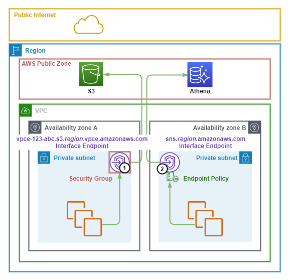
The following points summarize the above diagram.
- Interface Endpoints 1/2 are deployed into private subnets in AZ-A/B of the VPC. The are assigned an IP address from the Subnets they reside in.
- Endpoint 1 provides Private access to the S3 Service and has a Security Group applied that limits access to the Endpoint.
- Endpoint 2 provides Private access to the SNS Service and has an Endpoint Policy applied that limits which SNS resources that it can access.
- Endpoint 1 is accessed by the auto-generated Regional DNS name vpce-123-abc.s3.region.vpce.amazonaws.com which points to the Private IP address of the Endpoint.
- Private DNS is enabled for Endpoint 2 and the Public service DNS name sns.region.amazonaws.com now points to the Private IP address of the Endpoint.
VPC Peering
VPC peering allows you to connect two VPC's together via an encrypted virtual link.
The following points list the characteristics of VPC Peering.
- VPCs can be peered within the same region OR between different regions.
- VPCs can be peered within the same account OR between different accounts.
- To create a VPC peering connection, the requestor initiates a connection from the source VPC. The acceptor accepts the connection from the destination VPC.
- VPC peering connections are non-transitive. A VPC CANNOT be transited to reach another VPC or external connection via an Internet Gateway, S2S VPN, Direct Connect, etc..
- VPCs with overlapping CIDR ranges CANNOT be peered.
- Route tables MUST be configured to forward traffic between the VPCs.
- Security Group references can be used with VPC peering connections in the same region.
- Cross account Security Group references are possible within the same region. However, the Account ID is included when specifying the Securint Group ID. EG: acn-12345/sg-67890
- Optionally, Public Hostnames can be configured to resolve to Private IPs across a VPC peering connection.
VPC Flow Logs
VPC Flow Logs capture Metadata about traffic flows in and out of a VPC.
Flow Log Sources
Flow Logs are sourced from Elastic Network Interfaces (ENIs) and be enabled in 3 locations for a VPC.
The following table lists the 3 locations of VPC where Flow Logs can be enabled.
| Location | ENIs Captured |
|---|---|
| VPC | All ENIs in the VPC |
| Subnet | All ENIs in the Subnet |
| ENI | Only the specific ENI |
Flow Logs Destinations
Flow logs destinations can be either S3 or CloudWatch Logs.
The follow table list the Flow Destinations and their benefits.
| Destination | Benefits |
|---|---|
| S3 |
|
| CloudWatch Logs |
|
The following diagrams shows an overview of the VPC Flow Logs architecture.
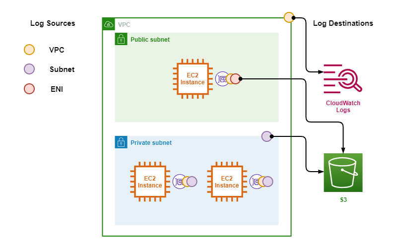
The following points describe the above diagram.
- Logs are sourced from Elastic Network Interfaces (ENIs) depending on where Flow Logs are enabled.
- The orange circle denotes Flow Logs enabled on the VPC were Logs from all ENIs are captured.
- The purple circle denotes Flow Logs enabled on the Private Subnet were logs from all ENIs in the Private Subnet are captured.
- The red circle denotes Flow Logs enabled on the ENI of the EC2 Instance in the Public Subnet, only this ENI caputed.
- Logs are forwarded to either S3 or CloudWatch Logs.
Flow Log Format
Flow Logs can capture Metadata on either ACCEPTED, REJECTED or ALL connections.
The following table lists example Flow Logs.
| version | account-id | interface-id | srcaddr | dstaddr | srcport | dstport | protocol | packets | bytes | start | end | action | log-status |
|---|---|---|---|---|---|---|---|---|---|---|---|---|---|
| 2 | 123456789010 | eni-1235b8ca123456789 | 172.31.16.139 | 172.31.16.21 | 20641 | 22 | 6 | 20 | 4249 | 1418530010 | 1418530070 | ACCEPT | OK |
| 2 | 123456789010 | eni-1235b8ca123456789 | 172.31.9.69 | 172.31.9.12 | 49761 | 3389 | 6 | 20 | 4249 | 1418530010 | 1418530070 | REJECT | OK |
Flow Logs have the following characteristics.
- Flow Logs are show in the order that they are evaluated
- If logs look to be part of the same flow and there is a ACCEPT followed by a REJECT it's likely due to a Security Group permitting inbound traffic and a NACL blocking outbound traffic.
- Security groups are Stateful so evaluate the Request and the Response as a single flow.
- NACLs are Stateless and see the Request and Response as 2 seperate flows.
- Flow logs are NOT realtime, there is a delay in the time between the traffic occuring and it being visible in the Flow Logs product.
Excluded From Flow Logs
Not all flows are logged and traffic to/from the following services are excluded.
- The VPC metadata service 169.254.169.254
- The VPC NTP service 169.254.169.123
- The Subnet DNS Resolver Network Address +2
- DHCP requests within a VPC
- Amazon Windows License Server
Traffic Mirroring
Traffic Mirroring is used to direct traffic towards a content inspection appliance.
Traffic Mirroring has the following characteristics.
- Mirror Sources are Elastic Network Interfaces (ENIs).
- Mirror Targets are an ENI, Network Load Balancer (NLG) or Gateway Load Balancer (GWLB).
- Filters are used to restrict which traffic is mirrored.
- A Mirror Session is the Source + Target + Filters.
- Network Load Balancers (NLB) are used to direct traffic from the Source to the Target for High Throughput and Availability.
- Mirrored traffic to a Network Load Balancer is encapsulated in VxLAN (UDP 4789).
- Mirrored traffic to a Gateway Load Balancer is encapsulated in GENEVE (UDP 6081).
- ENIs can be a Mirror Source or Target but NOT BOTH.
- VPC Flow Logs do NOT capture mirrored traffic.
- The Sources route table requires a route to the Target for the Inspection Applicance Subnet to receive Mirrored Traffic.
Links
https://learn.cantrill.io/courses/1231680
https://d1.awsstatic.com/whitepapers/aws-amazon-vpc-connectivity-options.pdf
https://docs.aws.amazon.com/vpc/latest/userguide/configure-subnets.html
https://docs.aws.amazon.com/vpc/latest/userguide/configure-your-vpc.html
https://docs.aws.amazon.com/vpc/latest/userguide/default-vpc.html
https://www.rfc-editor.org/rfc/rfc1918
https://docs.aws.amazon.com/vpc/latest/userguide/VPC_Route_Tables.html
https://docs.aws.amazon.com/vpc/latest/userguide/vpc-network-acls.html
https://docs.aws.amazon.com/AWSEC2/latest/UserGuide/security-group-rules.html
https://docs.aws.amazon.com/vpc/latest/userguide/vpc-nat-gateway.html
https://docs.aws.amazon.com/vpc/latest/userguide/flow-logs.html
https://docs.aws.amazon.com/vpc/latest/userguide/flow-logs-records-examples.html
https://docs.aws.amazon.com/vpc/latest/mirroring/traffic-mirroring-how-it-works.html
https://www.rfc-editor.org/rfc/rfc8926
https://docs.aws.amazon.com/vpc/latest/userguide/vpc-nat-gateway.html
https://aws.amazon.com/privatelink/
https://docs.aws.amazon.com/vpc/latest/privatelink/gateway-endpoints.html
https://docs.aws.amazon.com/vpc/latest/privatelink/create-interface-endpoint.html
https://docs.aws.amazon.com/vpc/latest/privatelink/aws-services-privatelink-support.html
https://docs.aws.amazon.com/vpc/latest/privatelink/create-interface-endpoint.html#vpce-private-dns
https://docs.aws.amazon.com/vpc/latest/peering/what-is-vpc-peering.html
https://docs.aws.amazon.com/vpc/latest/userguide/VPC_Route_Tables.html#gateway-route-tables
https://docs.aws.amazon.com/vpc/latest/userguide/VPC_Route_Tables.html#route-tables-priority